high-speed MEMS switch eye diagram performance
The eye diagram is a graphical representation of a signal's quality in digital communication systems. It is formed by superimposing multiple traces of a repetitive signal on a time axis. The resulting waveform resembles an eye, hence the name "eye diagram." The opening and closure of the "eye" correspond to the signal's timing and jitter.
The eye diagram is a critical tool in assessing the quality of digital signals. By analyzing the eye diagram, designers can quickly evaluate a signal's integrity and quality, including its timing, jitter, and noise. Additionally, the eye diagram can help identify and diagnose problems with signal transmission and reception, making it a valuable diagnostic tool in digital communication systems.
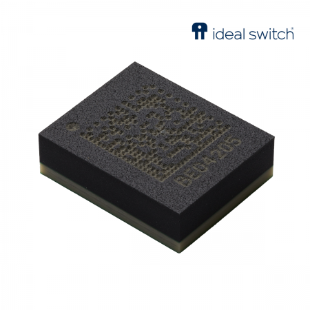
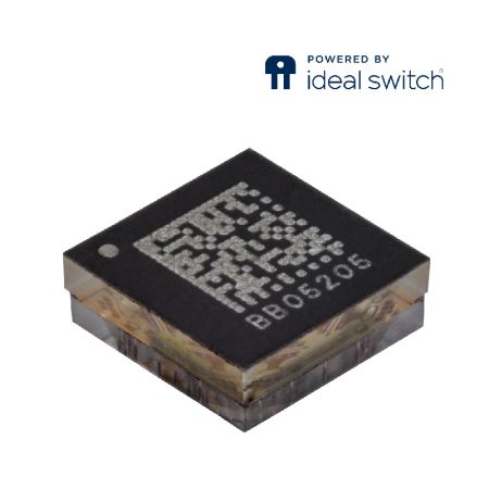
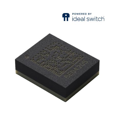
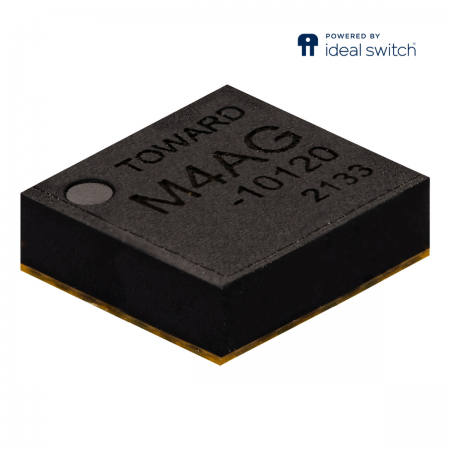
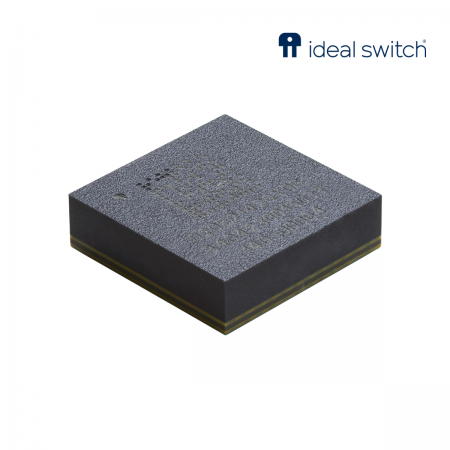
In 2021, Bright Toward launched the high-speed MEMS switch M4AG, powered by Menlo Micro's Ideal Switch, designed for high-speed signals applications. This article shares the eye diagram and high-frequency performance of high-speed MEMS switch M4AG.
Parallel bus vs. serial bus
Thanks to the rapid development of communication technology, electronic systems have shifted from traditional parallel buses to serial buses. There are many types of serial signals, such as PCI Express, USB, SPI, and so on. Why is the application of serial buses so widespread?
Several advantages of serial data transmission are as follows:
Reduced overall cost due to a lower number of signal lines
Serial data transmission solves the problem of transmission delays between traditional parallel data
Because the clock is inserted into the data, the problem of transmission delay between data and clock is eliminated
PCB design of transmission lines is relatively easier
Testing the signal integrity is also simpler."
Formation and Importance of Eye Diagram
The eye diagram contains rich information and can reveal the impact of noise such as intersymbol interference, allowing for a complete interpretation of the digital signal's characteristics and evaluating the quality of high-speed MEMS switches. Therefore, when selecting switches for use in high-speed IC test interface boards (load boards), the eye diagram analysis of the switches themselves is the core of the analysis of signal integrity in high-speed interconnect systems.
The Formation of an Eye Diagram
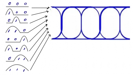
An eye diagram is the result of accumulating a series of digital signals with different binary codes according to a fixed pattern on the oscilloscope screen. As the oscilloscope has a persistence function, accumulating all the waveforms obtained according to each three bits will result in an eye diagram (as shown in the following figure).
Real-time waveforms vs. Signal eye diagrams
Compared to an eye diagram, a real-time waveform can reflect the details of the waveform, such as observing rising/falling edges, overshoot, monotonicity, etc. However, the eye diagram can reflect the overall characteristics of the signal passing through the MEMS switch.
Q: Is a good insertion loss representative of good signal quality?
A: Not necessarily; it can only be used as a reference.
Q: Is a beautiful eye diagram representative of good signal quality?
A: It can be, as the eye diagram results represent the overall quality."
M4AG Specs and eye diagram performance
DC to 16GHz (SP4T)
Power Handling: 9W per channel; Pulse 100W
IP3 > 90 dBm
Insertion Loss @ 16GHz: -3.0 dB (On Board Performance)
Return Loss @ 6GHz: -10dB (On Board Performance)
On-Resistance: 1Ω
Pff-State Capacitance: 15fF
3 Billion on/off Operations
ESD Rating: 2000V(HBM)
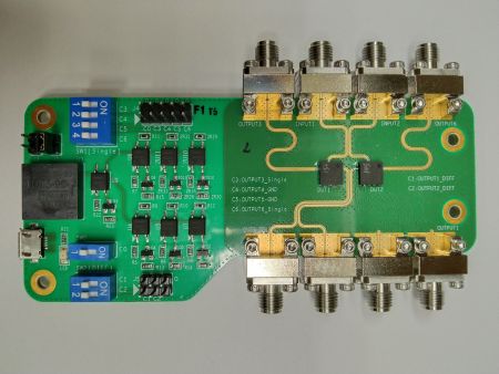
M4AG Differential Signal + Loopback Test Board Real Shot
This test board is designed to verify the RF characteristics and eye diagram performance of M4AG when using two switches to form a differential circuit and loopback path. It also provides customers with performance verification of our MEMS switch loading high-speed signals.
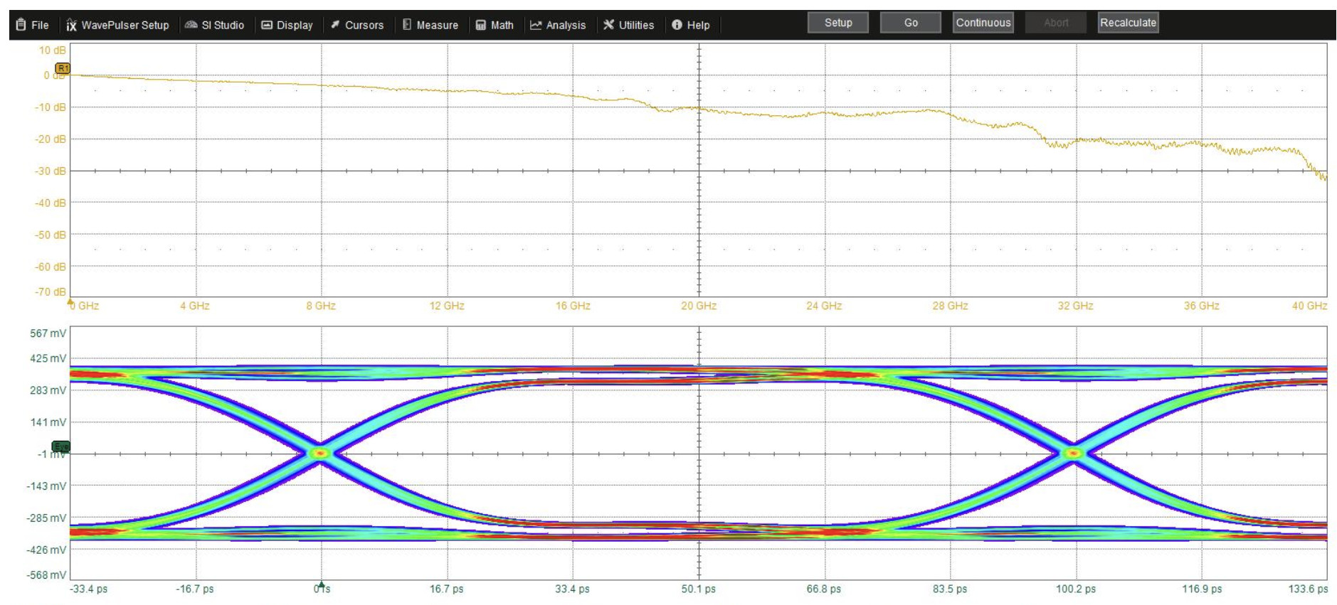
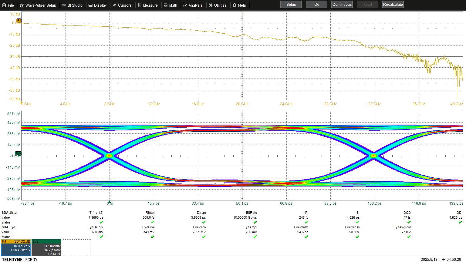
Eye Height: 607 mV
Eye Width: 94.6 ps
Jitter: 7.9593 ps
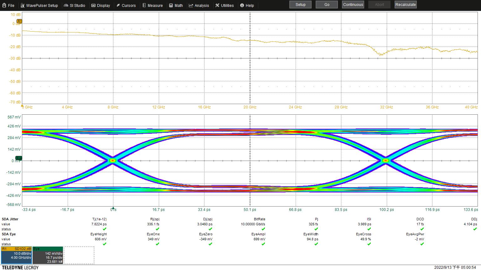
Eye Height: 606 mV
Eye Width: 94.8
Jitter: 7.8224 ps
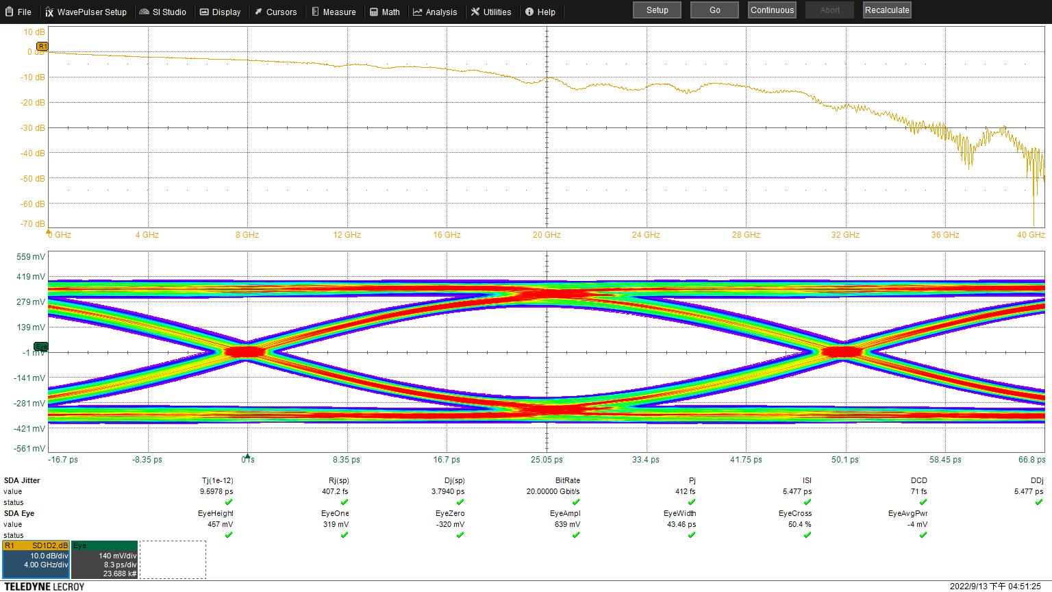
Eye Height: 457 mV
Eye Width: 43.46 ps
Jitter: 9.5976 ps
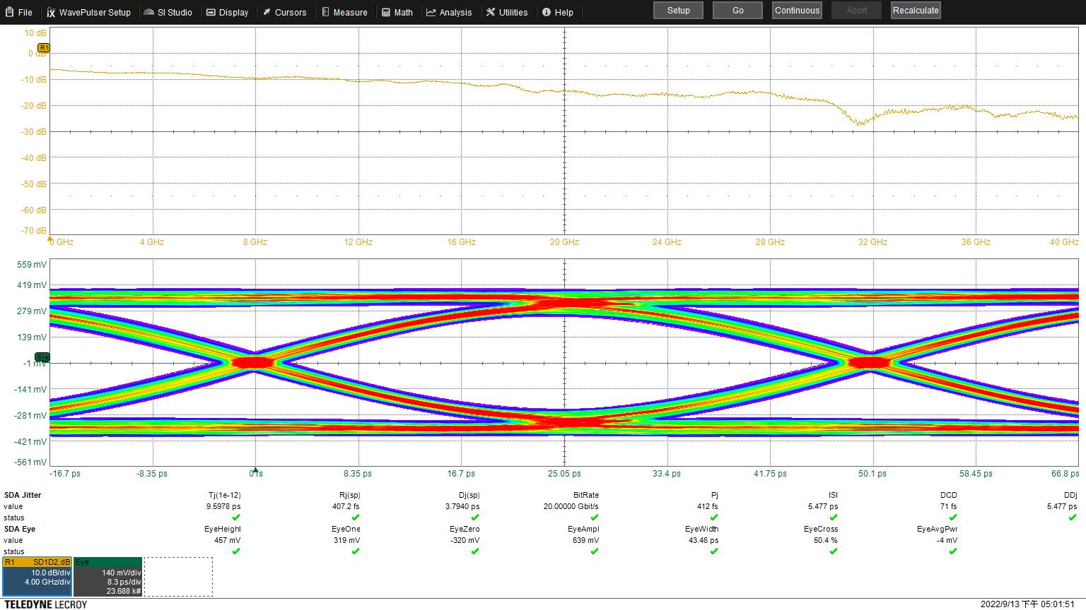
Eye Height: 457 mV
Eye Width: 43.46 ps
Jitter: 9.5978 ps
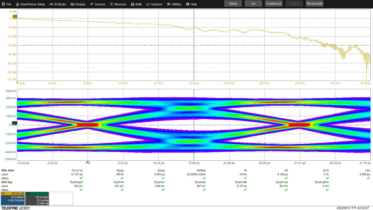
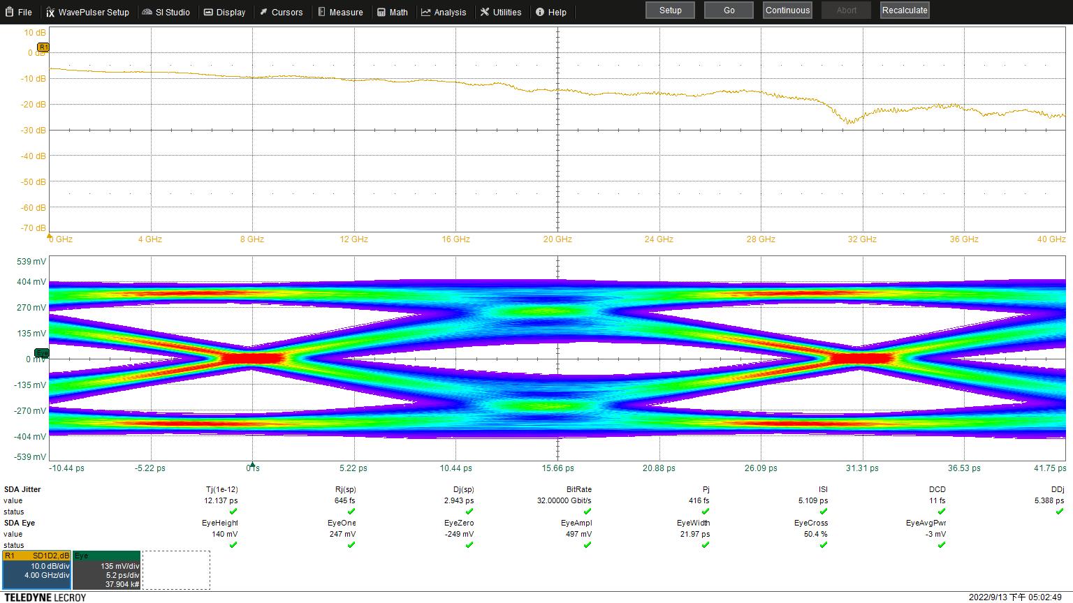
Eye Height: 135 mV
Eye Width: 21.97 ps
Jitter: 12.636 ps
- Related Products
8 GHz SP4T micro-mechanical RF MEMS Switch
MM5140
This high-power SP4T RF MEMS switch enables highly reliable switches capable of greater than 25 W forward power per channel as an SP4T from DC to 8 GHz....
Details Add to cart26 GHz SP4T micro-mechanical RF MEMS Switch
MM5130
This is a high-power SP4T micro-mechanical RF MEMS Switch. Our innovative technology enables highly reliable switches capable of greater than 25W forward...
Details Add to cartDC to 18 GHz, SP4T RF MEMS Switch
MM5120
This is a high-frequency (DC to 18GHz) SP4T micro-mechanical RF MEMS Switch. It is a highly reliable switch capable of greater than 25W forward power....
Details Add to cart16 GHz SP4T micro-mechanical RF MEMS Switch (ESD Enhanced)
M4AG
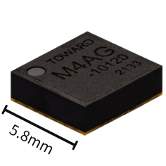
This is a High power SP4T micro-mechanical RF MEMS Switch (Length*Width*Height: 5.8*5.8*1.9mm). Each channel is capable of greater than 9W forward power....
Details Add to cart40 Gbps DPDT RF MEMS Switch
MM5600
This is a DPDT switch for high-speed differential signal switching. The MM5600 is based on Menlo Micro's Ideal Switch technology and can operate up to 40 Gbps...
Details Add to cart3 GHz SPST (6 channels) micro-mechanical RF MEMS Switch
MM3100
This is a high power (25W per channel) six-channel SPST micromechanical switch offered in a 6.0mm*6.0mm BGA package. Given its small form factor, significant...
Details Add to cart1Amps SPST (6 channels) micro-mechanical RF MEMS Switch
MM1200
This is a 6 Channel SPST micro MEMS Relay intended for power and signal switching applications in both DC and AC circuits. This MM1200 is capable of 1A per channel...
Details Add to cart

